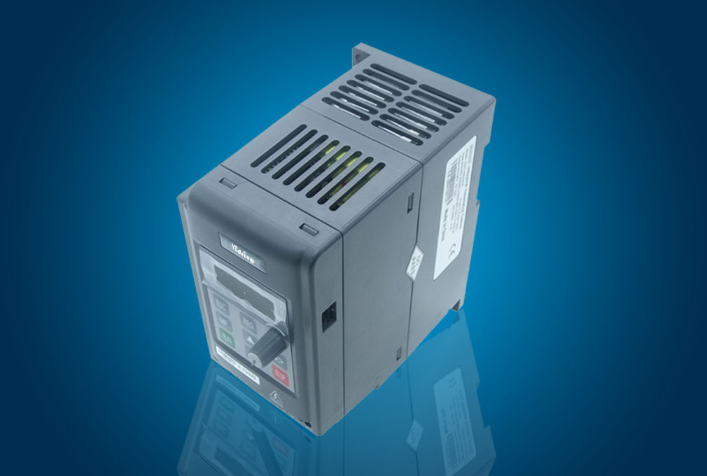
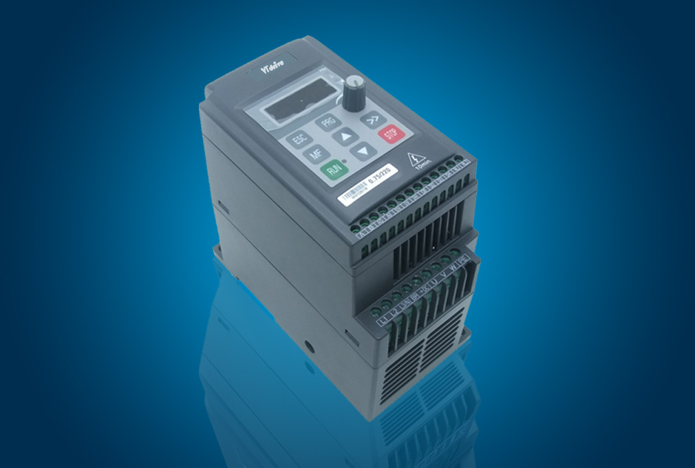
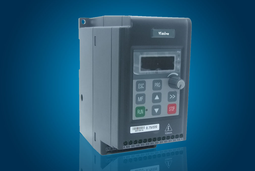
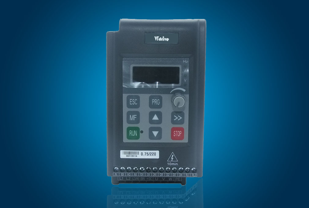
FI71 (Mini 220V)
Mini Type VFD for General Purpose
Mini Type VFD for General Purpose
1.1 Model reference

Figure1-1 FI71 Model description
1.2 Rating label
Figure1-2 FI71 Rating label
FI71 (Mini 220V)
Figure1-1 FI71 Model description

Figure1-2 FI71 Rating label
Power size of FI71 is referred to the standard 4 poles induction motor at rated voltage.
Overload: 150% rated output current, 1 minute
Table 1-1 220V rating data
Power supply: 220Vac~240Vac, 50Hz/60Hz, single/three phase | ||||
Model Name | Drive Power Size (kVA) | Rated Input Current (A) | Rated Output Current (A) | Motor Power (kW) |
1/3PH | ||||
FI71-20D00040 | 1.1 | 5.8/3.5 | 2.8 | 0.4 |
FI71-20D00075 | 1.7 | 11.3/6.3 | 4.5 | 0.75 |
FI71-20D00110 | 2.1 | 12.3/7.5 | 5.5 | 1.1 |
NOTE:
· FI71-21D00××× rating data are the same with FI71-20D00×××.
· FI71-20D means built-in bake unit, FI71-21D means without built-in bake unit.
1.4 Technical specifications
Table 1-3 General technical specifications
Input Power | Input Voltage Uin | 200V(−10%)~240V(+10%) 1/3PH 380V(−10%)~480V(+10%) 3PH |
Input Frequency | 48Hz~62Hz | |
Maximum Supply Imbalance | ≤3% | |
Power Output | Output Voltage | 0V~Uin |
Output Frequency | 0Hz~300Hz | |
Main Performance Function | Voltage Control | V/F, Open loop Vector Control |
Switching Frequency | 1kHz~15kHz | |
Adjust Speed range | Open loop vector -1:100, V/F mode -1:50 | |
Start Torque | 0.5Hz: 100% rated torque, 1Hz: 150% rated torque | |
Torque Accuracy | 7% | |
Torque ripple | ≤2% | |
Speed accuracy | ≤1%n (Under the rated operating conditions) | |
Reference Resolution | Digit- 0.01Hz, Analogue- 0.1%×Max. frequency | |
Accel. & Decel. Rate | 0.1s~3600s | |
Voltage Boost | 0.1%~30.0% | |
Overload | 150% rated output current, 1 minute | |
V/F | 4 types: V/F (user can program) and ramp (2.0 power, 1.7 power, 1.2 power) | |
DC Braking | Injection frequency: 0.0%~20.0% Max. frequency Injection current: 0.0%~300.0% rated current Injection time: 0.0s~60.0s | |
Dynamic Braking | Brake rate: 0.0%~100.0% | |
Jog | Jog frequency: 0.00Hz~50.00Hz Jog interval time: 0.1s~60.0s | |
Preset | 4 speeds (decided by control terminals) | |
AVR | Maintain the rated output voltage when the input power supply voltage changed. | |
Special Performance Function | Internal PID | Easy to form a closed-loop control system |
Control Terminal | Reference Source | Digit: display panel, motorized pot (E-Pot), PID, comms. |
Analogue: AI: 0V~10V, 0(4)mA~20mA, keypad potentiometer | ||
Operation Mode | Keypad, control terminals, serial comms. | |
Digital Input Terminals | DI1~DI4: programmable terminals | |
Analogue Input Terminal | AI: programmable terminal, 0V~10V, 0(4)mA~20mA, can be used as digital input terminal by programming | |
Analogue Output Terminal | AO: programmable terminal, 0V~10V, can be used as digital output terminal by programming | |
Status Relay | 1 programmable relay, contactor data: AC250V/2A(COSφ=1) AC250V/1A(COSφ=0.4) DC30V/1A | |
Comms. | Connectors | Terminals A, B |
Protocol | Modbus RTU | |
Environment | Altitude | 1000m rated 1000m~3000m,1% rated current derating per 100m |
Operating Temperature | -10°C~+40°C | |
Max. Humidity | ≤90%RH, no-condensing | |
Vibration | ≤5.9m/s2(0.6g) | |
Storage Temperature | −40°C~+70°C | |
Running Environment | Indoor, non-flammable, no corrosive gasses, no contamination with electrically conductive material, avoid dust which may restrict the fan | |
Protection | Output shortage, over current, over load, over voltage, under Voltage, phase loss, over heat (heatsink and junction), external trip, etc. | |
Efficiency | ≥89% | |
Mounting Method | Surface mounting, DIN rail | |
Enclosure | IP00, IP20 (by adding optional device) | |
Cooling Method | 0.4kW model is nature cool, others are forced air cool | |

Figure 2-2 Mechanical dimensions and mounting

Figure 2-8 Typical cabling