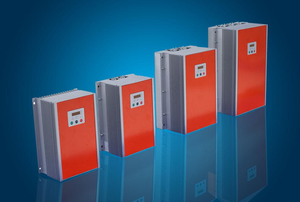
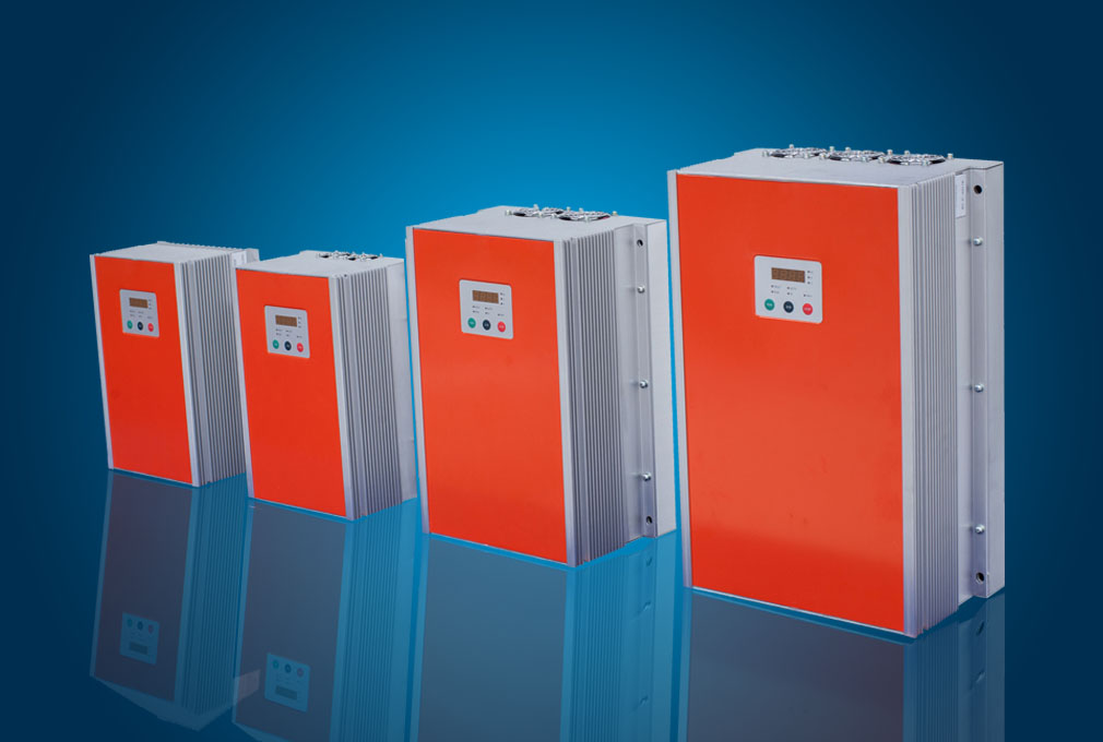
1.3 Product Series
RS−P−4D□□□
Power (kW) | 600 | 800 | 1200 | 1700 | 2500 | 3600
| 5000 | 6600 | 7700 | 12K | 17K
| 21K | 23K | 33K
| 40K |
| Motor | Power (kW) | 0.55 | 0.75
| 1.1
| 1.5
| 2.2
| 3 | 4 | 5.5
| 7.5 | 11 | 15
| 18.5 | 22
| 30 | 37 |
Voltage | Three phase 220V/480V (*0~480V adjustable) |
Current | 50/60Hz (*0~300V adjustable) |
DC Input
| Power | 1.1
| 1.5
| 2.2 | 3
| 4.2 | 5.5
| 7.5
| 10
| 14
| 21
| 27
| 33
| 39 | 54
| 65
|
| Voltage | DC 430V±50V | DC 530V±50V |
MPPT Range
| 260~380V | 370~630V |
Out | Current | 3
| 5 | 7 | 7 | 11 | 17 | 13 | 13 | 18
| 24 | 30
| 39 | 45
| 60
| 91 |
| Voltage | Three phase 220V/380V(*0~480V, adjustable) |
| Frequency | 50/60Hz(*0~300 Hz, adjustable) |
Cooling Mode
| Self-cooling | Forced air convection cooling OR water convection cooling |
*Some parameters change under the parameters of the actual input voltage, radiation, etc.
 1.4 Technical Specifications
MPPT | V&T RS−P inverter have maximum power point tracking (MPPT) |
*Vector | Realizing AC motor decoupling, enabling the DC motorization of operation control
|
* Frequency setting mode | Operation panel setting, terminal UP/DN setting, host computer communication setting, analog setting AI1/AI2/AI3, terminal pulse DI setting |
Frequency range | 0.00~60.00Hz 0.00~300.00Hz Upon the control mode of vector 0.0 ~3000.0Hz, which can be customized according to the customer demand |
Startup frequency | 0.00~60.00Hz |
Acceleration/ deceleration time | 0.1~36000s *:Operation panel setting, |
POWER SUPPLY | DC Power; 3PH AC 380~ 480V power |
Extended function | Features customization, integration with other devices and industrial applications, features customization, overheating of the motor overload sensing, and an external digital sensor |
Protection function | Stall protection, under voltage, over current protection, over voltage protection, the protection module, heat sink over-temperature protection, controller overload protection, motor overload protection, output short circuit to ground exceptions, the output phase anomalies, overload protection, and many other hardware protection |
Efficiency | At rated power,93%~98% |
Environment | Operating site | The product shall be mounted vertically in the electric control cabinet with good ventilation. Horizontal or other installation modes are not allowed. The cooling media is the air. The product shall be installed in the environment free from direct sunlight, dust, corrosive gas, combustible gas, oil mist, steam and drip |
Ambient temperature | -10 ~ +40ºC, derated at 40 ~ 50ºC, the rated output current shall be decreased by 1% for every temperature rise of 1ºC |
Humidity | 5~95%,no condensing |
Altitude | 0 ~ 2000m, derated above 1000m, the rated output current shall be decreased by 1% for every rise of 200m |
Vibration | 3.5mm,2~9Hz;10 m/s2,9~200Hz;15 m/s2,200~500Hz |
Storage temperature | −40~+70℃ |
* Operating function code must use operating panel , by a trained professional and technical personnel.
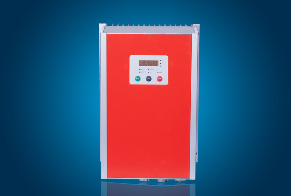
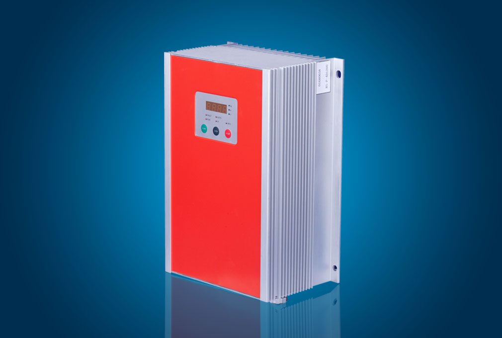
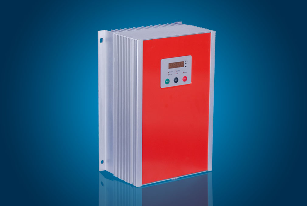
1.5 Product Component Name

1.6 Product Outline, Mounting Dimension, and Weight

Inverter model | Outline and mounting dimension (mm) | Approximate weight (kg) |
W
| H | D | W1 | H1 | D1 | Mounting hole diameter |
RS−P−4D600 ~ RS−P−4D1700 |
217
|
347 |
136 |
203 |
269 |
4 |
8.5 |
5
|
RS−P−4D2500 |
RS−P−4D3600 | 217
| 352 | 148 | 203 | 269 | 15.5 | 8.5 | 8 |
RS−P−4D5000 | 217 | 352 | 148 | 203 | 269 | 15.5 | 8.5 | 8 |
RS−P−4D6600 | 257 | 412 | 178 | 243 | 326 | 46 | 8.5
| 15 |
RS−P−4D7700 | 257 | 412 | 178 | 243 | 326 | 46 | 8.5
| 15 |
RS−P−4D12k |
302 |
491 |
178 |
288 |
404 |
46 |
9 |
20 |
RS−P−4D17k |
RS−P−4D21k ~RS−P−4D280k | Custom-made cabinet |
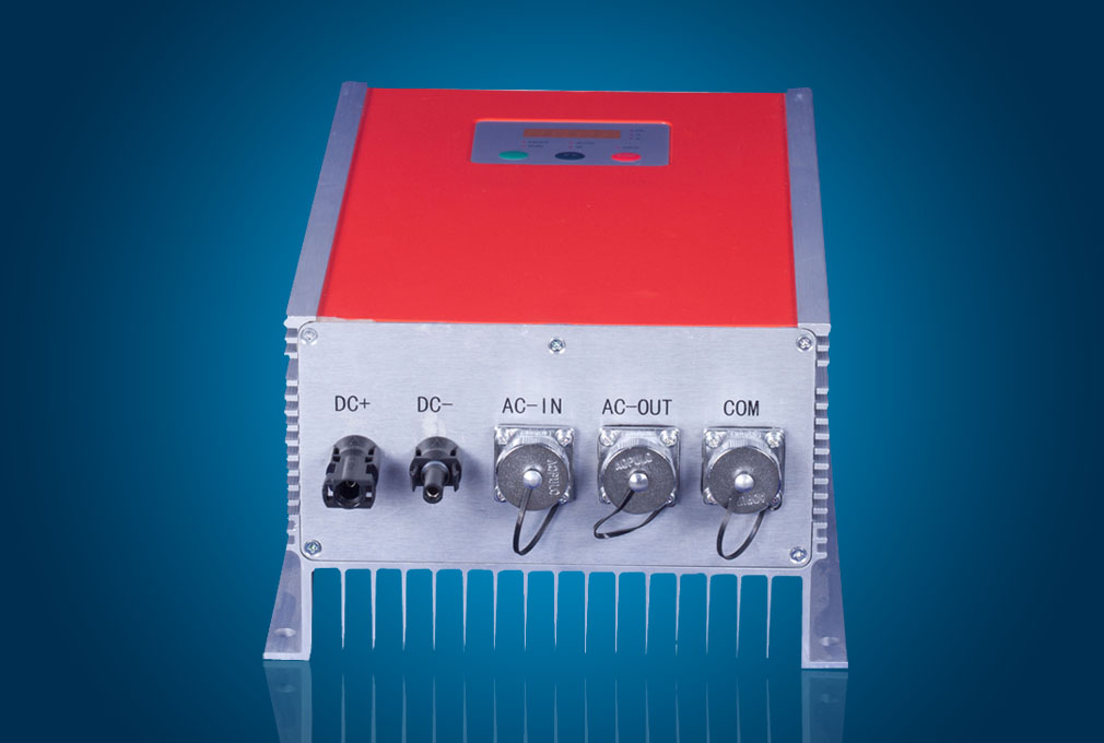
1.7 Inverter Wiring
The following figure shows increased spare AC power supply, solar energy and three-phase AC input power connection diagram to prohibit the supply of two inputs at the same time