FIT-Closed Loop VFD
FIT Series Inverter -General Purpose Use
FIT Series Inverter Introduction
1.1 Naming and nameplate identification

FIT-Closed Loop VFD
FIT Series Inverter Introduction
1.1 Naming and nameplate identification
1.2 All the components of FIT series Frequency Inverter
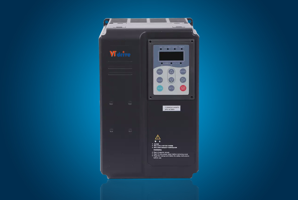
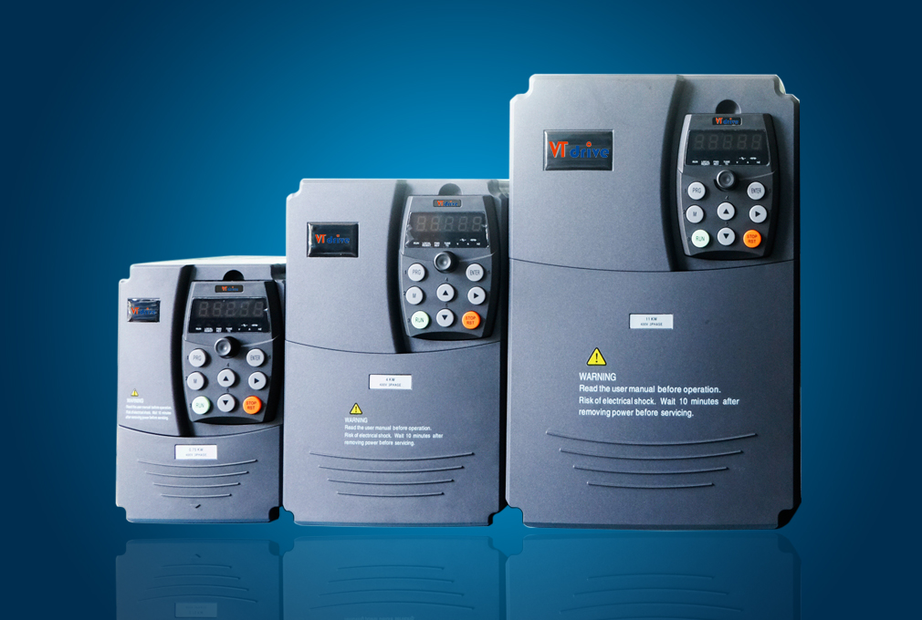
![]() According to voltage class and power level, FIT series Frequency Inverter can be generally classified into two structure types, namely, plastic structure and sheet metal structure.
According to voltage class and power level, FIT series Frequency Inverter can be generally classified into two structure types, namely, plastic structure and sheet metal structure.

The outline drawing of plastic structure of FIT series Frequency Inverter

The outline drawing of sheet metal structure of FIT series Frequency Inverter
According to voltage class and power level, FIT enclosure structure types are listed as the following table:
Voltage & Power Clas | Housing Type |
| Single-phase 220V | |
| 0.4kW ~2.2kW | Plastic housing |
| Three-phase 380V | |
| 0.75kW ~15kW | Plastic housing |
| 18.5kW ~315kW | Sheet metal housing |
1.3 Basic technical specification
Item | Specification | ||
Standard functions | Maximum frequenc | Vector contro: 0~300Hz; V/F control: 0~3200Hz | |
Carrier frequency | 0.5kHz~16kHz The carrier frequency is automatically adjusted based on the load features. | ||
| Input frequency resolution | Digital setting: 0.01Hz Analog setting: maximum frequency x 0.025% | ||
Control mode | • Sensorless flux vector control (SFVC) • Closed-loop vector control (CLVC) • Voltage/Frequency (V/F) control | ||
| Starting torque | • G type: 0.5 Hz/150% (SFVC); 0 Hz/180% (CLVC) • P type: 0.5 Hz/100% | ||
Basic functions | Speed range | 1:100 (SFVC) | 1:1000 (CLVC) |
Constant-speed accurac | ± 0.5% (SFVC) | ± 0.02% (CLVC) | |
Torque control accuracy | ± 5% (CLVC) | ||
Overload capacity | • G type: 60s for 150% of the rated current, 3s for 180% of the rated current • P type: 60s for 120% of the rated current, 3s for 150% of the rated current | ||
Torque boost | • Fixed boost • Customized boost 0.1%–30.0% | ||
V/F curve | • Straight-line V/F curve • Multi-point V/F curve • N-power V/F curve (1.2-power, 1.4-power, 1.6-power, 1.8-power, square) | ||
V/F separation | Two types: complete separation; half separation | ||
Acceleration /deceleration curve | • Straight-line ramp • S-curve ramp Four groups of acceleration/deceleration time with the range of 0.0–6500.0s | ||
DC braking | DC braking frequency: 0.00Hz~maximum frequency Braking time: 0.0s~36.0s Braking action current value: 0.0%–100.0% | ||
JOG control | JOG frequency range: 0.00–50.00 Hz JOG acceleration/deceleration time: 0.0–6500.0s | ||
Simple PLC and multi-speed operation | It implements up to 16 speeds via the simple PLC function or combination of DI terminal states. | ||
Onboard PID | It realizes process-controlled closed loop control system easily. | ||
Automatic voltage regulation (AVR) | It can keep constant output voltage automatically when the mains voltage changes. | ||
Overvoltage/ Overcurrent stall control | The current and voltage are limited automatically during the running process so as to avoid frequent tripping due to overvoltage/overcurrent. | ||
Quick current limiting | Maximize overcurrent failure and protect the Frequency Inverter in normal operation | ||
Torque limit and control | It can limit the torque automatically and prevent frequent over current tripping during the running process. Torque control can be implemented in the CLVC mode. | ||
Individualized functions | High performance | Control of asynchronous motor and synchronous motor are implemented through the high-performance current vector control technology. | |
Power dip ride through | The load feedback energy compensates the voltage reduction so that the AC drive can continue to run for a short time. | ||
Rapid current limit | It helps to avoid frequent overcurrent faults of the AC drive. | ||
Timing control | Time range: 0.0–6500.0 minutes | ||
Multi-motor switchover | Four motors can be switched over via four groups of motor parameters. | ||
Bus support | Support field bus: Modbus | ||
Motor overheat protection | The optional I/O extension card enables AI3 to receive the motor temperature sensor input (PT100, PT1000) so as to realize motor overheat protection | ||
Multiple encoder types | Support difference, open collector and rotary transformer | ||
Operation | Command source | Operation panel, control terminal and serial communication port are given Switch in various methods | |
Frequency source | Various frequency sources: digital reference, analog voltage reference, analog current reference, pulse reference and serial port reference. The switching can be conducted in various methods | ||
Auxiliary frequency source | 10 kinds of auxiliary frequency source. The auxiliary frequency jog and frequency synthesis can be achieved flexibly | ||
Input terminal | Standards: 7 digital input terminals, among which one support maximum high-speed pulse input of 100kHz 2 analog input terminals, among which one only supports voltage input of 0 ~10V and the other supports voltage input of 0 ~10V or current input of 4 ~20mA Expansion capability: 3 digital input terminals 1 analog input terminal, which supports voltage input of -10V ~ 10V and supports PT100/PT1000 | ||
Output terminal | Standards: 1 high-speed pulse output terminal (The open collector type is optional), supporting 0~100kHz square signal output 1 digital output terminal 1 relay output terminal 1 analog output terminal, supporting current outpout of 0~20mA or voltage output of 0~10V Expansion capability: 1 digital output terminal 1 relay output terminal 1 analog output terminal, supporting current output of 0~20mA or voltage output of 0~10V | ||
Display and keyboard operation | LED display | Display the parameter | |
Key lock and function selection | Realize partial or all key lock and define the action range of some keys to prevent misoperation | ||
Protection function | Short circuit test of electrified motor, input/output default phase protection, overcurrent protection, overvoltage protection, undervoltage protection, overheat protection, overload protection, etc | ||
Options | IO expansion card, differential input PG card, OC input PG card and rotary transformer PG card. | ||
Environment | Service site | Indoor, free from direct sunshine, no dust, corrosive gas, combustible gas, oil fog, water vapor, drip or salt, etc. | |
Altitude | Less than 1,000m | ||
Ambient temperature | -10℃~ +40℃ (Please use the equipment by derating at ambient temperature of 40℃~50 ℃) | ||
Humidity | Less than 95%RH, no water condensation | ||
Vibration | Less than 5.9m/s2(0.6g) | ||
Storage temperature | -20℃~ +60℃ | ||
IP grade | IP20 | ||
Pollution level | PD2 | ||
Power distribution system | TN , TT | ||
1.4 Wiring mode of control loop of Frequency Inverter